Wiring and Lighting Issues
My aim was to produce a model that
runs reliably with directional constant lighting and simulated gyralights.
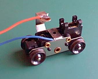
Close examination of the construction
of the trucks showed that electrical continuity on the model as purchased relies
upon

|
|
the
weight of the frame bearing on the top of a bare metal pivot plate on each truck, and |
|
|
a
riveted joint between the pivot plate and the bare metal truck frame which supports the
wheel bearings. This riveted joint was loose enough to allow the truck to pivot in
an end for end manner |
| The model as
purchased was running smoothly. The two weaknesses I have identified may be more perceived
than real, nevertheless I decided to 'hard wire' the trucks to minimise the
development of any future continuity problems. I did so by soldering hookup wire to
the joint between the pivot plate and the truck side members as indicted by the blue wire
in the accompanying photo. |
 |

Lighting
I have been tossing
around ideas about constant lighting. In some discussions I have detected a swing
back to lighting modules in parallel with motors rather than fed from diodes in series
with motors. Some modellers are concerned about the loss of the first 2.1 volts to
the motor when three diodes are used in each direction - two to provide the voltage of
1.4v for the bulbs and one to permit the lights to be directional. I prefer the idea
of reserving some voltage for lighting in this manner rather than have the motor begin to
turn before the lights come on.
For lighting I have
chosen Mitey Lites by Circuitron. They are 1.5v high output and are tiny enough to
fit in 1.5mm holes in the shell or light castings. I am using eight such bulbs.
2 for the headlights at each end and two for the gyralights at each end.
Each pair of headlights
will be fed off a pair of diodes in series with the motor with a third diode to determine
direction.
I have experimented with
a circuit to provide directional high-low brilliance to simulate the gyralights and I have
included the circuit diagrams on links below. I can't claim too much originality.
These circuits are a cobbling together of bits 'n' pieces from other circuits I
have found published in data sheets and on the web.
I have mounted the the
directional constant lighting diodes and the two gyralight simulation modules (one for
each end as I want them to be directional as well) on a strip of .040" three ply on
which I have 'breadboarded' the components. It was intended to be experimental so
that a PC board could be drawn up from the bread board layout, but it is working
just fine as it is and I see little point in disturbing it even though it looks a bit
'Heath Robinson'.
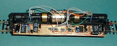
This photo was taken
when I had the bulbs mounted on the circuit board. In fact they proved to be too
fragile to be placed into the bulb holders with tweezers when the circuit board was
mounted in the shell and I lost about ten of them over several sessions of fitting and
removal of the board. I have now mounted the bulbs (there are eight of them) in the
shell with their leads being soldered to small pc boards epoxied to the inside of the hood
ends and with small jumper wires soldered between these pc boards and the main circuit
board. It means a soldering job to remove the circuit board, but it should not
often be necessary.
You will note that I
have discarded the cast ballast weight. Some sheet lead will be glued to the inside
of the shell to compensate for some of this lost weight.
The two circuit diagrams
may be accessed from the links in the following paragraph:
The underlying Directional Constant Lighting circuit is well known but there are a
couple of extra features. The diagram shows how the Gyralight
Modules interface with the basic circuit to provide directional gyralight
operation. This requires two complete modules to be built and the extent of the
circuitry for each can be gauged from the photo above which has a module at each end of
the circuit board. There is also a 1K resistor across the 2 sets of three diodes
that make up the directional constant lighting part of the circuit. I use a feedback
controller which relies on being able to detect a back EMF signal from the motor and the
diodes prevent that current from being detected. This resistor provides a bypass for
the back EMF signal without adversely affecting the operation of the lighting
circuit.
A few pointers about the
circuits:
The dimness of the
'off cycle' of the gyralights is determined by the resistor between the collector and base
of the 2N3906. I have found the 22R to look right to me. Increasing this value
will further dim the light. Reducing the value will brighten the light.
Leaving the resistor out altogether results in a complete on/off flashing - but there are
cheaper ways to do that!
The regular bright
flash that simulates gyration will be dulled if there is not 1.6 to 1.7 volts at the
output of the LM317. In one of my modules the specified value of 68R produced 1.7
volts but in the other it did not and I had to substitute a value of 75R to produce that
voltage. The circuit is clearly sensitive to tolerances in the manufacture of the
components used and a little experimentation may be necessary to achieve the result you
want.
Similarly I had to
substitute a capacitor. The value of 270 mfd between pins 2 and 8 of the LM3909 IC
produced 'gyrations' at 55 per minute in one module. In the other I had to
substitute 330 mfd to achieve the same rate.
The LM3909 is now
obsolete but may still be found in some electronics stores. A pin for pin compatible
IC, NTE876 is thought to be a direct substitute, but I have not tried one yet.
The voltage regulator
part of the circuit specifies a 25v 220 mfd capacitor. The only ones I had (or found
at the local electronics shop) were unacceptably large. I had some small 16 volt
jobs though and have used them. I can't imagine that I will exceed the 16 volt
rating but if I suffer an internal explosion I'll know that I have been pushing the
limits! The remaining capacitors are all in the low voltage part of the
circuit and I have used 3.3 volt and 5 volt capacitors simply because I had them on hand
from a wrecked VCR.
A hard lesson learned
Had I known that the
fitting of lighting would have involved so much handling of the shell I would have sorted
it out much sooner in the building process. I now have a shell with some rather
battered detail parts and more paint chips and abrasions than I can call weathering so I
have some patching up to do. Once that is done, the loco will be finished and
I'll see if I can make a short AVI file of the gyralights. It will hinge on my
ability to get an adequately sharp focus on my older technology digital camera which can
record a brief series of AVI frames. If it works, you'll see it here.
Return
to main page