 |
Baldwin S-12 in H0 Scale SP #1451 as seen in 1953 |
 |
|
Baldwin S-12 in H0 Scale SP #1451 as seen in 1953 |
|
![]()
But why?
About mid way through 2001 I decided to take the plunge and convert to DCC whilst I was still in the early stages of preparation of my loco stud for service. 'Preparation for service' typically means taking an undec loco and customising it to a specific prototype. Recent raising of the bar for ready to run models will no doubt mean that I am able to get some models into service more quickly, but I also have a heap of boxes of locos to work on. Haven't we all?!
I decided to use #1451 as my guinea pig to learn about the installation and operation of DCC at a basic level. I duly fitted her with a TCS T1 decoder and programmed her to show full intensity lights in direction of travel and dimmed in the opposite direction. The only snag I struck was that the running qualities were not what I was expecting. She was OK, but not brilliant on a feedback DC controller and I knew she could run better if I replaced the old, old Athearn motor (it is a very old loco) with a modern skew wound motor. I chose a Mashima 1833 because its shaft length is OK as a drop in fit using the original Athearn drive train. The only modification needed was a pair of bushes to take up the difference in shaft diameter (Mashima 2.0mm, Athearn 3.2mm)
The modifications I made to the shell for full profile air tanks and the consequent trimming down of the Athearn chassis meant that it was no longer suitable for an 'A-Line' style conversion. Looking it over I concluded that a new chassis built up from brass would not be a major job - and so it has proven. The whole project took about five evenings spread out over about a month. It could have been quicker had I been in the position to give more than fleeting attention to the task.
Has it been worth it? Absolutely! #1451 now crawls at a walking pace and has a smooth transition to running speed.
Here's a step by step explanation of what I did:
|
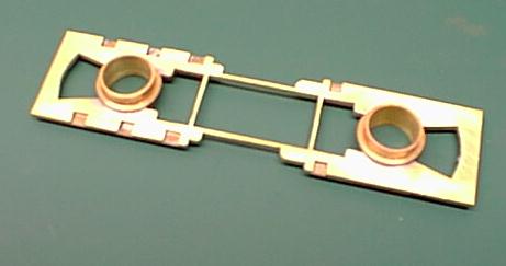
The base of the chassis is a sandwich of two layers of 1.0mm sheet brass. This image shows the two layers having been sweat soldered together after fretting out locating slots in the top layer. The cutaway areas to clear the air tanks on each side have been formed and the brass has been marked out for the areas to be cut out for the trucks and motor mounts. The brass turnings will form the truck mounts as shown below. | 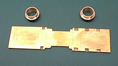 |
|
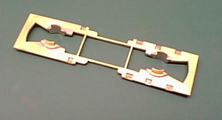
The cutouts for the trucks and motor now formed with a piercing saw and cleaned up with needle files. |
|
|
Piercing saw? In response to my first posting of this page I have been asked what a piercing saw is. Hopefully a picture is worth a thousand words! It may be called a jeweller's saw in some places, I think. I use blades of about 60 teeth per inch. I'm ham fisted. I used about six blades by the time I completed this chassis. |  |
|
The brass turnings soldered to the base chassis. The lip was formed part way down the turnings to define the height at which the chassis would sit relative to the trucks. |
|
|
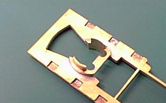
The excess part of the turnings removed with a piercing saw leaving just the side sector pieces for the trucks to clip into. |
|
|
Retainer plates fitted to 'fine tune' the height at which the trucks will sit relative to the chassis. If you use a live chassis then this plate will also carry the current from the horizontal plate on top of the truck. Later in the process I filed these plates down even more to eliminate any possibility of shorting from the wheels |
|
|
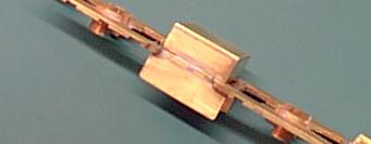
Coupler mounts fitted. These will receive Kadee 58s with the 'ears' cut off the draft gear boxes. The channel sides are to keep the draft gear boxes aligned fore and aft as they will be held in place with screws that must not be over tightened. Those screws also serve to secure the shell to the chassis. The cut away portion of the thin cross member is to clear the wire from the bottom motor brush whilst retaining enough of the cross member to define the location of the motor. | 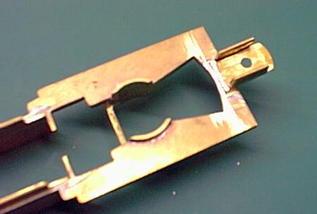 |
|
1.0 mm brass sheet motor locators fitted to the upper part of the chassis. These form a slot that the motor is a snug slide fit within. Towards the bottom of these locators are further 1.0mm thick bearers fitted to the inside of the main locators. These are approximately level with the top of the main chassis plate and form bottom stops for the motor sides to maintain the shaft at the correct height for the drive train. Those parts continue down below the bottom of the chassis plate and, with their length trimmed as shown form mounts for the fuel tank to be fitted. | 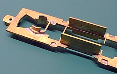 |
|
The fuel tank was formed from pieces of 1.0 mm brass sheet and soldered in place over the mounts described in the previous section. |
|
|
The fuel tank was filled with sheet lead about 1.5 mm thick and a small brass retaining bar soldered in place on each side. The motor will be finally held in place with double sided adhesive tape applied to that 'stack of lead' | 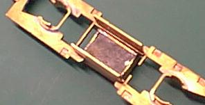 |
|
Does it work? The motor and drive train jury rigged to test for smoothness of operation. It passed with flying colours on pure smoothed DC so DCC should be a breeze. | 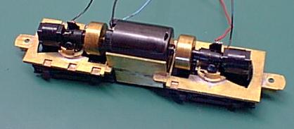 |
|
And so to DCC. I wanted to provide a firm base for the decoder rather than risk it flopping about on to a flywheel. I have made this platform from .7 mm brass. It has one end contoured to fit the top of the Mashima motor and will be secured by double sided mounting tape and the decoder will be secured to the flat section, also with mounting tape. | 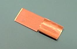 |
|
The finished job! I had intended that the decoder would fit on top of the brass mounting plate described above but my calipers proved to be a bit elastic when I took the measurements! I have taped the decoder under the mounting plate and there is still clearance between it and the top of the plastic worm housing. At the other end the two truck wires look dangerously close to the flywheel. In fact there is plenty of clearance but I think a plastic shield over the flywheel would be good insurance.
|
 |
|
|
The flywheel clearances are more evident in this broadside shot. Hmmm, the paintwork needs a little touch up in places. Knew I should have been more patient letting it harden before re-assembly. | 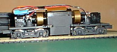 |
![]()
Updated for chassis rebuild December 2001