 |
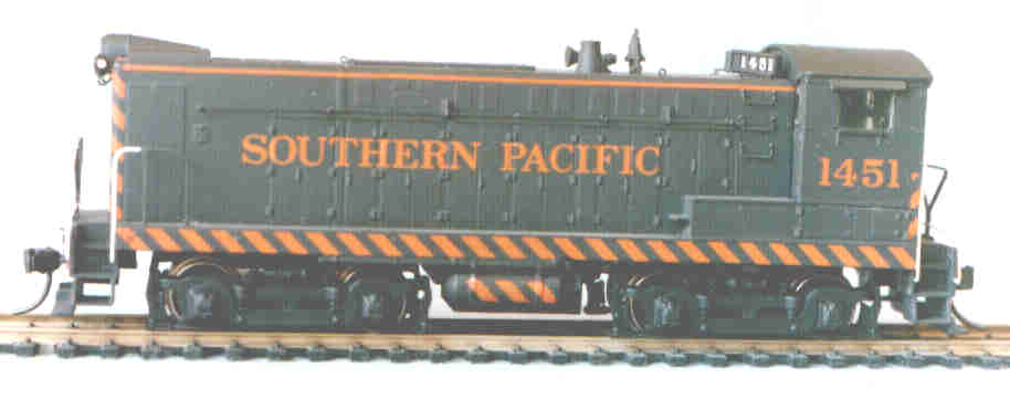
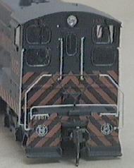
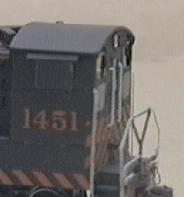
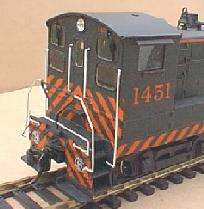
Baldwin S-12 in H0 Scale SP #1451 as seen in 1953 |
 |
|
Baldwin S-12 in H0 Scale SP #1451 as seen in 1953 |
|
![]()
|
|
|
![]()
| Desired end point: | SP S-12 #1451 as shown in 1970 SP Motive Power Annual at page 14. |
| Livery: | Tiger Stripes |
| The starting point: | An undecorated Athearn S12 |
![]()
![]()
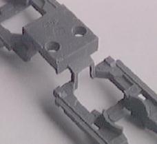
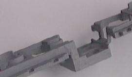
Modifications to Athearn Chassis:
| Cut away coupler mounting pads to permit body mounting of KD couplers |
|
|
| Cut away enough of the motor mount 'well' to enable fully formed air tanks to clear the chassis. The amount I cut away from each side of the chassis was about 26mm long by 6mm wide for the full depth of the 'well' casting. This results in the chassis having what looks to be a severely weakened structure at one end of the motor mount - but I think it will withstand normal careful handling. It may not withstand a fall to the floor from layout height - but then neither would much else of the loco! | ||
|
|
| Replaced wheel sets with NWSL turned, plated wheels. |
![]()
Electrical:
| Fitted directional constant lighting with diode matrix mounted behind radiator grille. | |
| Fitted Tamya 1.5v 'grain of wheat' bulbs to 3mm i/d aluminium tube for both headlight and rear light to prevent unwanted light 'spillage'. | |
| Fitted lighting harness with plug to enable body to be separated from chassis | |
| Motor hard wired by soldering wires from truck pick ups (including the 'ground' pads) to a segmented pc board strip epoxied to the top motor brush retaining strip. This wiring runs via the lighting harness and plug in the case of one lead, of course, to accommodate the constant lighting circuitry. |
![]()
Shell Modifications
: |
Removed large 'step' behind cab and repaired the void with .8mm styrene sheet. | ||
| Fabricated small step from styrene sheet and fitted below cab rear door. | |||
| Chassis mounting slots in side sills filled with styrene strip since removal of the chassis material has done away with the usual Athearn shell mount. | |||
| Sunshades fabricated from styrene strip. | |||
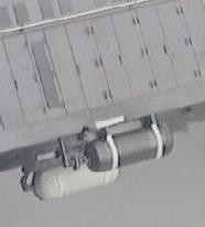
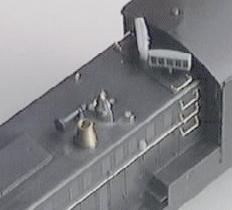
| Flat plane material removed from around the air tanks on both sides of shell and piping cleaned up to make it 'see through'. Air tanks made full 3D by laminating 6.5mm styrene rod slit to half round section, ends shaped to match moulded tank halves on shell and applied to back of those tank halves to make fully formed tanks. (Raid the knitting kit for 6.5mm needles for this one - but don't get caught!) |
|
||
| Horn modified so that it is anchored only at the back, cleaned up and made to look finer. | |||
![]()
Commercial details added:
| DA 1105 | Hood side lift rings. I know, they are EMD but they look right to me. |
| DA 2202 | Hand grabs |
| DA 102203 | Brass nbw sets (they are beautiful) |
| DW 128 | Bell |
| KD #5 | Couplers |
| PS 31661 | Number boards |
| MV 21 | Headlight lenses |
| MV 300 | Marker light lenses |
| PS 31333 | Marker lights |
| SV 102 | Handrail tees |
| MS 87-71 | Tiger Stripe decals |
| .010" Wire | Guitar string for hood side handrails and coupler lift bars |
| .015" Wire | Hard brass wire for end and cab handrails |
| Hypo tube | 0.7mm o/d hypodermic tube (.015" i/d) |
![]()
Fabricated parts:
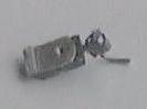
| Conical style stack turned in brass. | ||||
| Coupler lift bars from .010" guitar string (DA ones were found to be not the right length) | ||||
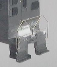
| Front side walkway handrails formed from hard brass wire of .015" dia using Smokey Valley plastic tees for the top union of the centre upstand with the top of the rail. Walkway mounts made by gluing small styrene pads to the edge of the walkway (about 1mm x 2mm x .25mm thick) and drilling through the pads and the whole thickness of the side sill to accept short lengths of hypodermic tube with about 1mm standing proud of the walkway. The two rearmost .015" upstands were then super glued into these fittings and the front upstand fitted to the side of the step. | 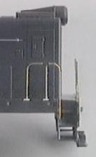 |
|||
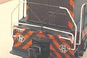
| The end, pilot beam mounted rails were fabricated from .015" hard brass wire for the main rail, .012" brass for the the rail that runs parallel to and just above the top edge of the pilot beam and brass strip of .8mm x .25mm section for the diagonally shaped frames that support the main rails. The 'foot' of these bars, joined in the middle, were soldered to a 3mm length of .8mm x .8mm brass angle stock which, inverted, forms a mounting bracket in the middle of the top edge of the pilot beam and provides the appropriate offset to enable the main handrails to remain in a flat plane and yet fit to the front face of the pilot beam adjacent to the steps. | ||||
|
|
|||
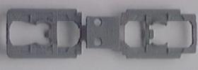
| Coupler mounting pads built up from sheet styrene and brass to allow KD number 5 coupler boxes to be body mounted. I made the pads flush with the bottom of the cast on protruding curved draft gear fitting and the last layer of the built up pad is 1.6mm brass sheet, tapped 2.0mm to accept a coupler mounting screw which doubles as the means of attaching the body to the chassis and found that correct coupler height was obtained by using a .5mm strip of brass between the coupler mounting pad and the coupler box. | ||||
| This brass strip, the same width as the coupler box extends back about 3 mm to the rear of the coupler box and provides the means of clamping the shell to the chassis when the couplers are fitted. | ||||
![]()
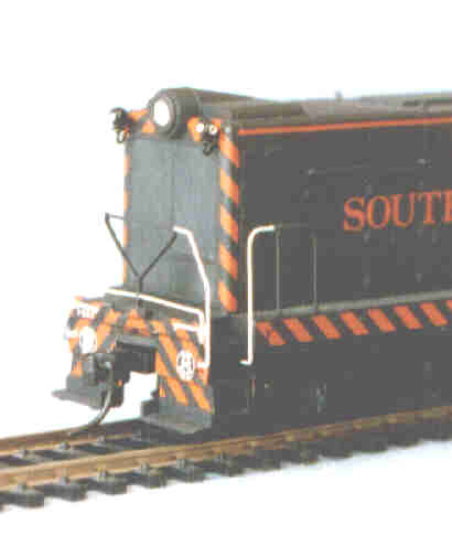
Known Errors:
| It's a 'fatty'. It shows mostly on the too narrow cab front windows. | |
| The lifting rings should not have been fitted to the hood top. The Athearn shell had a representation of lift rings which I carved off and replaced with DA wire ones. I later found that there should be no hood top lift rings. I could remove them - but they look cute, so, for the moment anyway, they stay! | |
| The hatch at the bottom right hand of the radiator grille should not be on this model. I judged that the surgery to remove it would be likely to spoil the shell. | |
| This particular loco should have the narrower side sill with no notch for the fuel tank filler. Again, I found this late in the conversion process, after painting and decalling and have decided to live with this inaccuracy at least until the shell requires any major maintenance, if ever. |
![]()
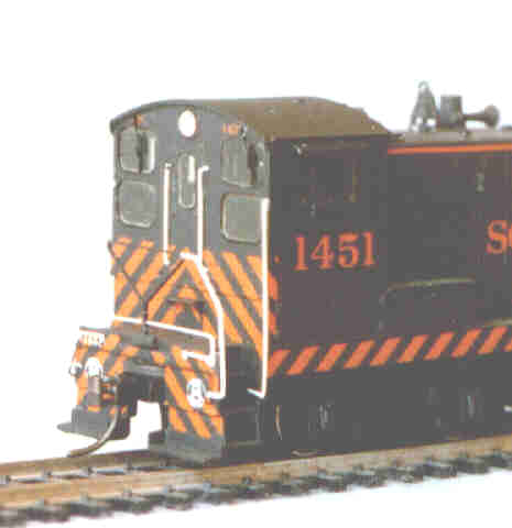
The Frustrations:
| Finding out about detail differences once well into the project. This is always a possibility, of course, even when you think you have researched your loco. | |||
| The glazing! I have had five attempts at glazing. I'm still not 100% happy with
the result, but it is time to move on and as my techniques improve it will be possible to
do a retrofit of new glazing later. The technique that worked best of the five attempts was to use .015" sheet acetate (part of a keyboard shipping cover) chosen for its lack of surface blemish. I covered both sides of the acetate with removable grade self adhesive label paper to protect the surface and to make it easier to mark out. I used some DA S-12 glazing components as templates for the corner shapes which I roughly cut with a blade and finished off with wet and dry paper. I held each pane with a toothpick with a small blob of Blu-Tak on the end and offered each up to its aperture in the cab. Once I was satisfied with the fit I removed the label paper from each pane and secured it by brushing a light film of white (PVA) glue on the window frame and carefully placed the pane with the toothpick and Blu-Tak. My dissatisfaction with the present glazing relates to some visual awareness of the edge of the panes in parts. The photos do not show this up very well. Had Krystal Klear been available I would have used it and maybe avoided this visual disturbance. I think that a fine line of KK run around the beading edge later will fix it. |
|||
|
|
||
![]()
Thanks for spending this time with me.
I welcome constructive criticism or helpful hints
by email.Nelson Kennedy, Christchurch, New Zealand
![]()
Original page completed August 1997. Updated for chassis rebuild December 2001